A few weeks ago, some friends and I decided that our houses weren’t crammed full enough with useless crap and so we embarked on a journey to a large junk shop surplus warehouse. The place was a vast hangar brimming with old and curious pieces of technology ranging from IBM keyboards to VHS video editing suites. They even had a sinister sounding machine called a “DNA synthesizer” but that sounded too Dr Evil for me to mess with.
After an hour of scrabbling around we left with various bits of over-priced detritus from the bygone days of technology which we then had to find some justification for purchasing during our journey home. My haul consisted of a rain damaged VT-100 keyboard (no justification needed, obviously) and a heavily soiled wooden keypad from an old alarm system. Here’s what it looked like after cleaning it up: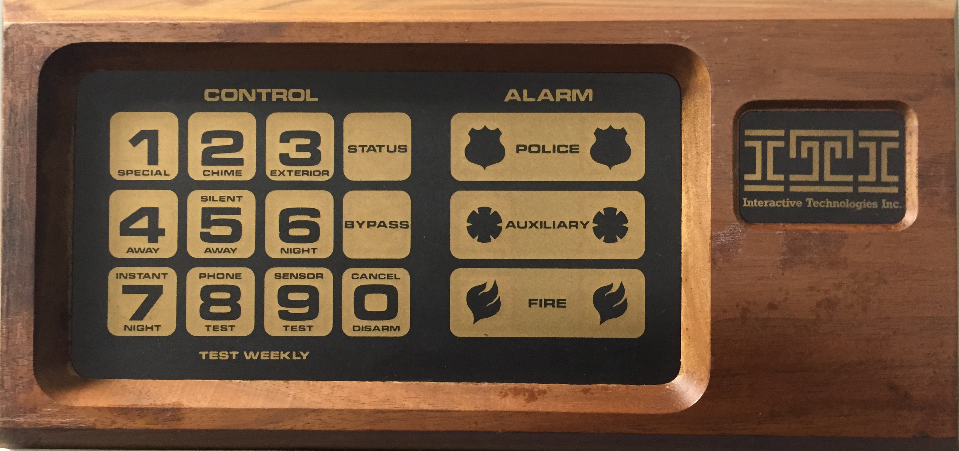
The geekier among you will appreciate some of the reasons why it stood out to me: the real wood frame; the wonderful Star-Trek Motion Picture typography; the flat futuristic keys; the “modern” ITI logo proudly displayed on the right. The idea of hooking it up to a real-world alarm system in 2015 was utterly appealing.
Here’s the back. Note the distinct lack of guts and the note alluding to its previous owner’s gun collection:
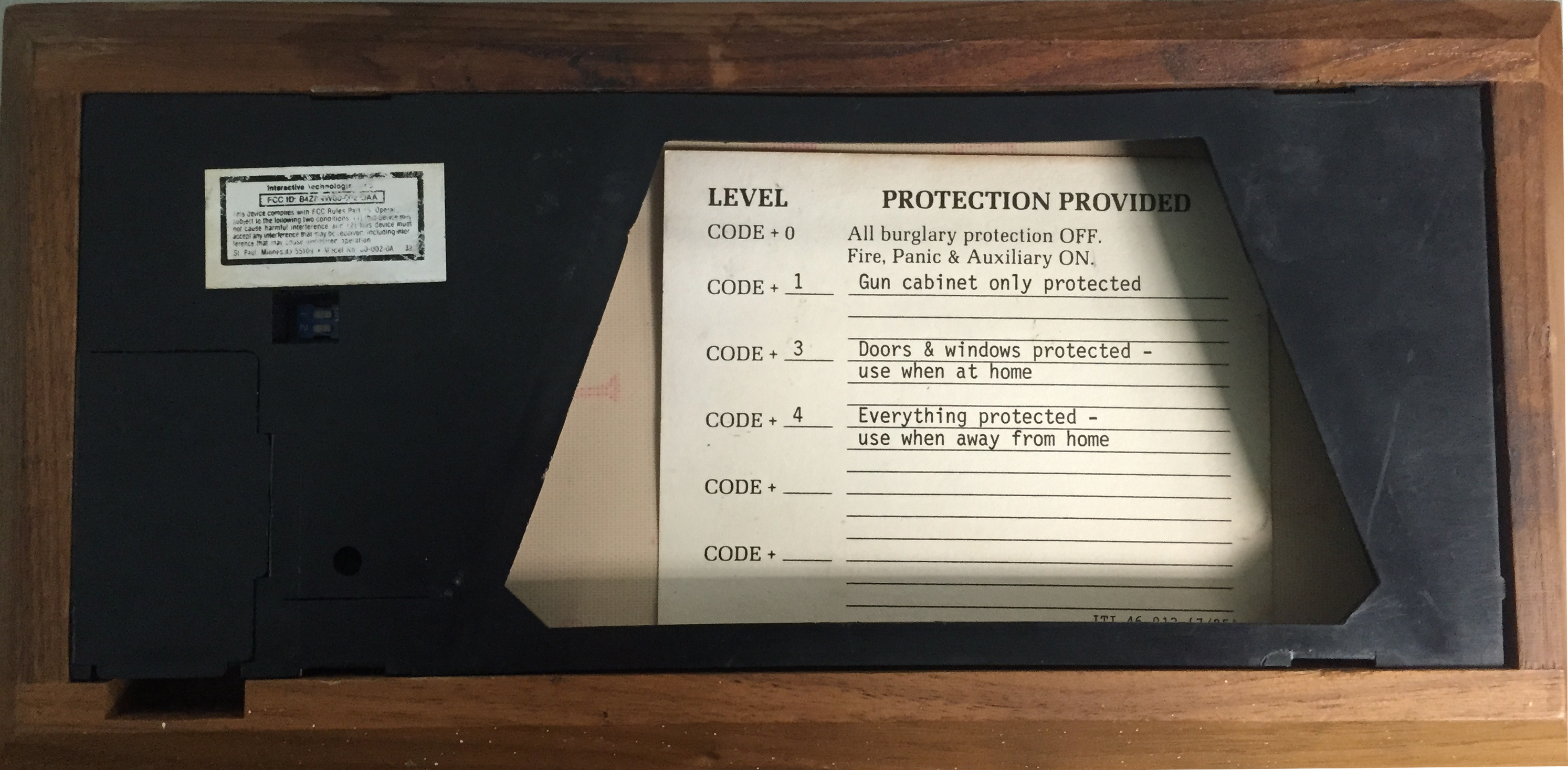
I’d envisaged the former owner being some sort of back-woods buck-toothed survivalist who spent his life protecting his family from the oppressive government until he got sick and had to sell his house, guns and alarm system to pay for his medical bills.
I took it apart expecting to find screw terminals for power and an alarm loop but was surprised to find a corroded 9V battery and a handful of components:
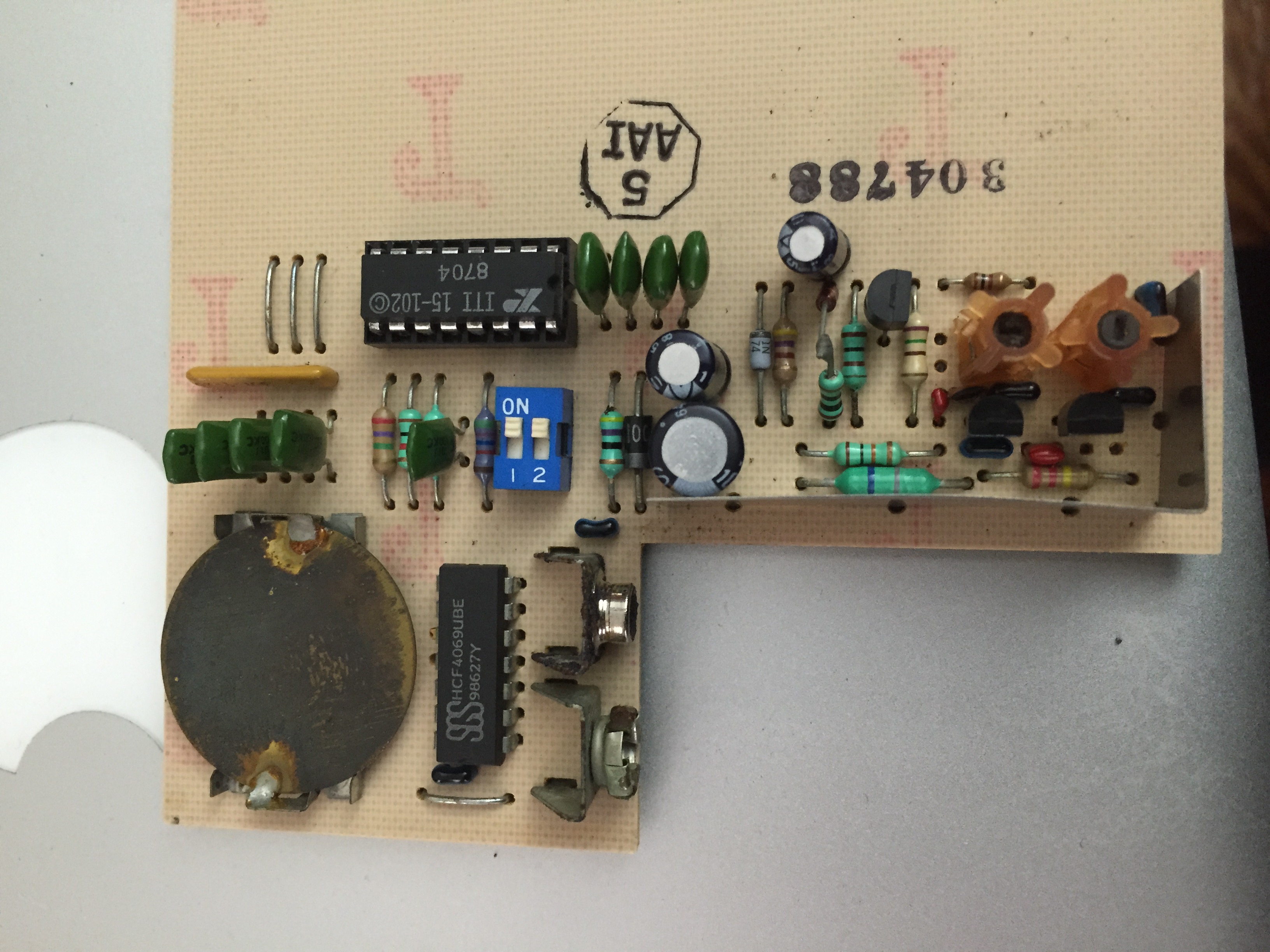
So its power is self-contained, and there was no sign of any way to connect it to an alarm loop. So how did this thing work? It has some inductors and a bunch of caps, but surely it can’t be wireless – it looks way too old for that – it’s made from wood for Bob’s sake!
A colleague pointed out the FCC-IC label on the back and suggested I look it up; this turned out to be a piece of genius.

With some fuzzy searching of the visible numbers on the sticker I eventually found its entry on the FCC website. So it was a wireless alarm panel, dating from 1986 and registered to use two RF bands: 319MHz and 340MHz.
Fortunately, the bands specified were well within the range supported by my $17 RTL-SDR and so I figured I could use it in an attempt to decode any signals this piece of vintage gear may be transmitting. After installing a fresh 9V battery to the keypad it was comforting to hear that the rusty old piezo speaker was still capable of beeping in response to keypresses! So I fired up gqrx in order to find any trace of signal from the keypad. After some searching around the 340MHz band I found some signals being sent by the keypad in response to the keypresses. Worryingly, the frequencies used by the keys were drifting all over the shop – my assumption remains that this is just as a result of the dodgy, aging analogue oscillators rather than this being part of the protocol, because the drift appeared to be unrelated to which key was being pressed.
The next step was to try and get some idea of what was actually being transmitted. So after finding a suitable center frequency, I ran the rtl_sdr command line tool to capture some raw I/Q data:
rtl_sdr -g 18 -f 340900000 -s 2000000 vintage.raw
and then pressed each button on the keypad in order.
Now, as far as radio is concerned I am a dilettante and have only a vague working knowledge of how complex quadrature signal processing works so you may find yourself cringing at my approach here on in. Let me know if you have any tips.
The RTL-SDR uses a very simple format for its raw I/Q output that can be very easily loaded into audacity for visual inspection. I hear you cringing already. Bear with me. Importing it as unsigned 8-bit stereo audio like so:
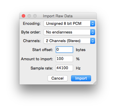
will let you see the I/Q as separate channels. Here is what my keypresses looked like:
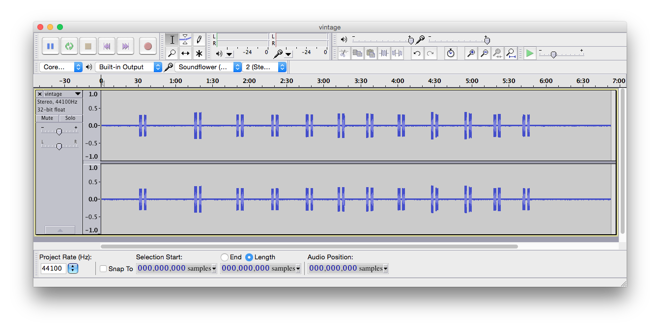
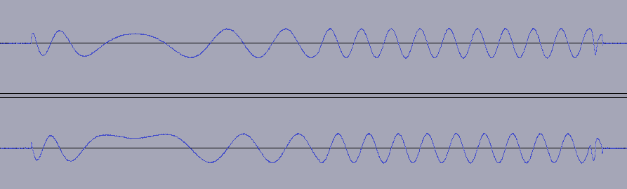
So it looked like each keypress resulted in two signals being transmitted. After zooming in on the first two transmissions the pattern became very clear – this was a simple On/Off Keying protocol where each keypress sends two identical 8-bit binary patterns consisting of long and short bursts of a fixed frequency. Here is what is sent when the “1” key is pressed:

Now, when I say a “fixed frequency”, I think that was the intention. The bursts vary widely and with a deeper zoom you can see diabolical things like this:
and…this abomination:
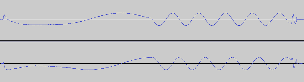
Again, I’m pretty sure that’s not deliberate.
You can really hear the problem when you play this as an audio file:
Link
Now we have a very simple protocol of 8-bit patterns that should be trivial to decode with the SDR despite frequency variation.
So I wrote a simple program, called cletus that takes the raw output of rtl_sdr and attempts to process it. Referring to Audacity, I noted down the bit patterns for each of the key-presses and coded them into a map.
The first thing cletus does is to convert the complex signal data into real data by taking the RMS of the signals and filtering it. The top trace here shows the RMS. The bottom shows the same signal after some simple filtering is applied:

It then uses a simple state machine to decode the short and long pulses into zeros and ones. Once it has 8 of them it outputs the keypad key it corresponds to, or if there isn’t one it just outputs the byte. Running it against the raw capture file produces this:
$ ./cletus vintage.raw

cletus - vintage ITI keypad decoding tool

e.g. rtl_sdr -g 10 -f 340900000 -s 2000000 - | ./cletus

1 1

2 2

3 3

Status Status

4 4

5 5

6 6

Bypass Bypass

7 7

8 8

9 9

0 0
And Bob’s your uncle.
The source, together with the raw capture file detailed above, is freely available on github if you want to mess around with it.
That’s enough for nonsense for now.